Copyright © Dongguan EMHEATER Electrical Equipment Co., Ltd. All Rights Reserved. Site Map

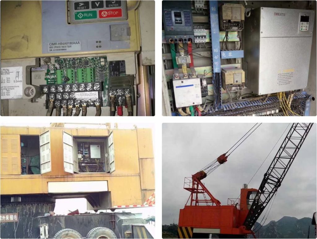
1. EM15-G3-090 replaces the technical requirements for on-site control of the Yaskawa H1000 crane:
1) When starting the frequency converter, it is required to have a large low-frequency starting torque and a smooth start.
2) Start time is 3.0s (0-maximum frequency 100HZ), stop time is 5.0s (maximum frequency 100HZ-0HZ)
3) Requirements for shutdown: Accurate positioning and no hook slipping.
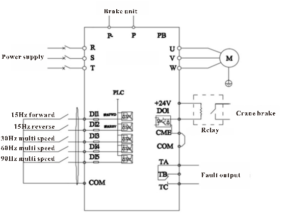
4) The main lifting motor requires four speed controls, starting forward and reverse at 15HZ. The first section is 30HZ, the second section is 60HZ, and the third section is 90HZ to improve on-site operation efficiency.
5) The lifting site environment is harsh, requiring the frequency converter to have a wide voltage range, withstand harsh dust, high temperature, and other tests.
2. Principles of on-site control
1) When starting, DO1 outputs a collector signal to the small intermediate relay, which then controls the motor's holding brake (opening the holding brake during operation and closing the holding brake when stopped)
2) Braking control during the descent process of the main crane: The equipment undergoes frequent forward and reverse rotation, acceleration and deceleration, and braking operation during startup. Therefore, the frequency converter often switches between the 1.3 and 2.4 quadrants, especially during heavy load descent when the motor is dragged by a heavy object to maintain its speed in line with the rotating magnetic field and exceed the synchronous speed. At this time, the motor changes from an electric state to a power generation state, and excessive regenerative energy is fed back into the frequency converter by the stator, This leads to an increase in the voltage of the inverter bus, and at this time, the regenerative energy is consumed by the inverter P-external braking unit and resistor.
3) The combination of DI1-D15 has a total of four speeds, and the on-site requirement is to operate at a maximum of 90HZ to improve usage efficiency and ensure that the vehicle does not slip.
3. Field application wiring diagram:
4. Set parameters.
NO. | Code | Set parameter | Discreption | Remark |
1 | b0-02 | 1 | Terminal control |
|
2 | b0-03 | 6 | Multi-function |
|
3 | b0-13 | 100 | Maximum frequency |
|
4 | b0-15 | 100 | Frequency upper limit |
|
5 | b0-21 | 7 | Acceleration time |
|
6 | b0-22 | 7 | Deceleration time |
|
7 | b3-06 | 37 | Fault reset |
|
8 | b4-03 | 17 | Frequency-level detection FDT1 output | Relay controlled holding brake output |
9 | b4-22 | 2.00 | Frequency detection value 1 (FDT1) | Brake output frequency, exceeding the set value output |
10 | b4-23 | 0.00 | Frequency detection hysteresis 1 (FDT hysteresis 1) |
|
11 | C1-00 | 20 | 1 speed |
|
12 | C1-01 | 30 | 2 speed |
|
13 | C1-03 | 40 | 3 speed |
|
14 | C1-07 | 90 | 4 speed |
|
15 | d0-00 | Motor rated power | set according motor nameplate |
|
16 | d0-02 | Motor rated current | ||
17 | d0-04 | Motor rated spped |
NO. | Code | Set parameter | Discreption | Remark |
1 | b0-01 | 0 | Vector control |
|
2 | d0-00 | Motor rated power | Set according motor nameplate | Before self-learning, b0-02 needs to set keyboard control |
3 | d0-01 | Motor rated voltage | ||
4 | d0-02 | Motor rated current | ||
5 | d0-03 | Motor rated frequency | ||
6 | d0-04 | Motor rated speed | ||
Set d0-30=3, press RUN to auto-tuning after displaying TUNE on the screen, and wait for about 15 seconds for auto-tuning to complete | ||||
1 | b0-02 | 1 | Terminal control |
|
2 | b0-03 | 6 | Multi-function |
|
3 | b0-13 | Set according motor nameplate | Maximum frequency |
|
4 | b0-15 | Frequency upper limit | ||
5 | b0-21 | 10 | Acceleration time |
|
6 | b0-22 | 10 | Deceleration time |
|
7 | b3-02 | 6 | Multi-speed 1 |
|
8 | b4-02 | 17 | Frequency-level detection FDT1 output | Relay controlled holding brake output |
9 | b4-03 | 3 | Fault output |
|
10 | b4-22 | 2.00 | Frequency detection value 1 (FDT1) | Brake output frequency, exceeding the set value output |
11 | b4-23 | 0.00 | Frequency detection hysteresis 1 (FDT hysteresis 1) | |
12 | C1-00 | ~ | Starting frequency | DI1 and COM closed or DI2 and COM closed |
13 | C1-01 | 100 | High speed frequency |
|
14 | A2-05 | 0 | Voltage limit selection is disabled |
|